The T3 controllers use 'Inputs' to sense the real world conditions using temperature sensors, switches and various transducers. The signal comes into the controller in the form of a control signal known as either digital or analog. A digital input has two states, the on and off states while an analog signal varies gradually from 0 to 100% of full scale. The T3 controllers inputs are 'universal' in that any input can be software defined to operate as analog or digital.
The sensor signal conditioning hardware is also universal where many sensor types can be wired directly to the controller. Thermistors, dry contacts, 0-10V signals and 4-20ma signals can all be wired directly to the controller with no extra transducer or resistor dividers to add externally. With most controllers, selecting a signal type will require moving a jumper but on the T3 controllers this is set up in the software.
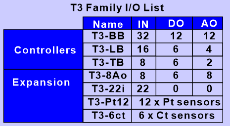
Each T3 controller has a fixed number of inputs and outputs on board as shown in the table below. The software can handle more I/O than is on board, to take advantage of this you can expand the controller with expansion modules to a maximum of 64 inputs and 64 outputs. When the application calls for more than this you'll need to add another controller. Data can be shared easily between controllers allowing the system to grow very large but its best to keep a particular system on a given panel to keep the system compartmentalized.
For adding expansion points to the controller I/O count please refer to the section on Expansion I/O
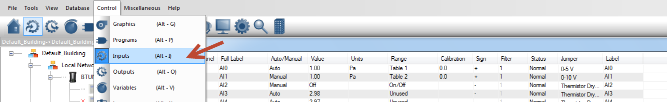
To get to the Inputs screen, hit Alt-I or click on the inputs icon in the menu system:
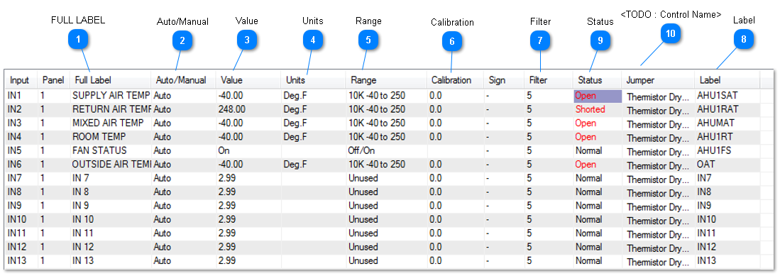
Sample Input work screen:
FULL LABEL
A unique twenty character descriptor used to identify the item throughout the system. Used for programming, trend logging, reports, and showing on the user displays.
The auto/manual field allows the operator override the real world conditions during commissioning and testing. Hitting the enter key with the cursor in this field will cycle the mode from auto to manual and back. Normally the input is in auto and the value will update according to the real world conditions. In manual mode, the value is fixed and the operator is in charge of the input and can type a new simulated value in the 'value' cell.
If you want to see how the rest of the system will respond when the outdoor air temperature hits 0C, 32F it is possible to simulate this condition by setting the value to 0C. First toggle the auto/manual cell to manual mode and then maneuver to the 'Value' field to enter the value you want to simulate, 0C in this example. Now the rest of the system will behave and operate as if the outdoor temperature is really at 0 Deg C. An alarm will be created after five minutes if the operator forgets to return the input to auto mode.
This cell shows the current value of the input. If the auto/manual field is in auto this will show the true real time data from the inputs. When the auto/manual setting is set to manual the value will stay at a fixed value. Assuming the mode is in manual mode, if the input has a binary range you can toggle between the two values by simply hitting enter on the value cell. When the input is configured as an analog item you can edit it by typing in a new value, again only when the item is in manual mode. Most of the time the input will be in auto mode and the value you see here will reflect the true conditions in the field.
The engineering units for the inputs, this field is fixed when you set the Range field. You can add custom engineering units in the 'custom tables' section.
The range setting is used to select the type of sensor connected to each of the inputs. There are many pre-defined ranges to select from, both analog and binary. The user can also define their own ranges using the custom range feature described further below.
To set the range highlight the field, press ENTER, and select either Analog, Digital or Custom Digital. Then enter the desired range number.
e) Cal.(Calibration)..The value in this field is added into the measured value to ad just for sensor in accuracy. The maxi mum correction is +/- 30. If the correction amount is between -3.0 and +3.0 there is 1 decimal point in the correction, otherwise there is no decimal point.
Calibration (CAL)Adds or subtracts an offset to the analog input readings for calibration purposes. In the example below, the input shows 24.1C but our reference sensor shows 25.1C, we enter a 1 in the calibration field and now the controller and meter values agree at 25.1C. The resolution of the calibration field is 1 decimal place. Use the 'Sign' field to change the offset to either a positive or negative value.
Filter is the number of samples that are averaged to give the value. A larger filter will slow the response of the system to a change at the input, but will filter out fluctuations that are not wanted.
Normal means the sensor is operating in the usual range. Open or Short means the input is short circuited, or open circuit. The cabling and sensor should be checked.