Outputs are the control points which send a signal from the T3000 out to the field devices like fans, pumps, dampers and valves. Outputs maybe either digital with two states such as with a fan or pump which can be on or off. Or they can be analog with continuously variable state such as with a damper motor that modulates from 0 to 100%. Each T3 controller can has a certain number of on board outputs, in the case of the BB there are 24 outputs which can be expanded up to a maximum of 64 outputs by adding expansion modules. Generally the system designer will try to keep all the control points for a particular machine or equipment room on the same controller. If there are more than 64 outputs in a project such as a large mechanical room with several chillers, pumps and valves working together, it is a simple matter to add another T3 controller and share a few variables over the network to create a seamless solution.
See the section titled Expansion Points for how to add expansion i/o to the controller.
TYPE OF MINIPANEL
INNER INPUTS
INNER DIGITE OUTPUTS
INNER ANALOG OUTPUTS
OUTER INPUTS
OUTER OUTPUTS
MP24
32
12
12
32
40
MP10
16
6
4
48
54
MP8
8
6
2
56
56
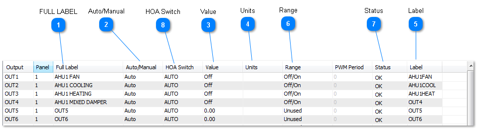
Sample Output work screen:
FULL LABEL
A unique twenty character descriptor used to identify the item throughout the system. Used for programming, trend logging, reports and so on.
A 20 character descriptor which is usually used to associate a given point with the physical location.
Use the auto/manual feature to temporarily take control of the input in manual mode, this is useful for commissioning and debugging. For example, if you want to see how the rest of the system will respond when the outdoor air temperature hits 0C, 32F, it is possible to simulate this condition. First move the cursor to the input which is set up to measure the outside air temperature for the building, then set the A/M field to manual and finally move over to the Value field to enter in the simulated temperature of 0C. When the testing is complete you must set the auto/manual field back to auto and the input will return to showing the actual outdoor temperature. The auto/manual field has only two states: Auto and Manual. Hitting the enter key with the cursor in this field will cycle the mode from auto to manual and back.
When in auto the out put will accept commands from Control Basic. When in manual the output will remain at a fixed value. To change from auto to manual or vice versa simply highlight the
The current value of the inputs. If the auto/manual field is in auto this will show the true real time data from the inputs. When the auto/manual setting is set to manual the value will stay fixed at whatever was last measured or written by the user.
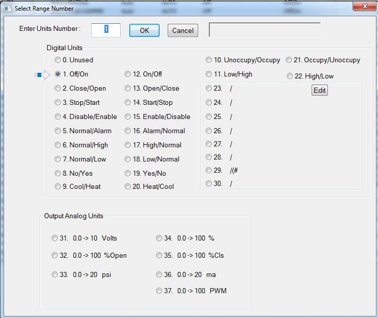
This field contains the value of the output point which may be digital or analog depending on the range selected. To toggle a digital value highlight the field and press ENTER. To change an analog value highlight the field and press ENTER followed by the new value and ENTER. Note that it is only practical to change an input value when the point is in manual.