Hot Key: Alt-L
KEYWORD: PID
Usage: 10 DAMPER1 = PID1
20 IF COOLING THEN VALVE1 = PID2
30 IF HEATING THEN VALVE1 = PID3
The PID Loop work screen is where you configure the PID loops and manage the pid terms. Once the PID loop is created in the grid it can then be referred to in the user programs to modulate dampers & valves. There are 64 PID loops in the T3 controller which leaves plenty of spares in the typical application.
A short programming example shows how the PID loops can be used in the user programs:
OUTPUT1 is a modulating damper called 'DAMPER1' and OUTPUT2 is the 'FAN1'.
Normally the damper will follow PID loop 1 as programmed in the first line.
The second line is evaluated next and overrides the earlier line, when the fan is off the damper will close.
10 DAMPER1 = PID1
20 IF NOT FAN THEN DAMPER1 = 0
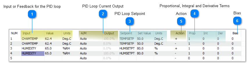
The following items describe the terms in the PID Loop work screen.
 Input or Feedback for the PID loop
These are the 'Inputs' or feedback for the PID loop, the sensors which are compared to the setpoint to calculate the response of the PID loop. A typical example is a temperature sensor in the chamber as shown above. PID loop 1 is a cooling PID loop and PID2 is a heating loop which both use the chamber temperature for the feedback. Type in the name of the sensor in the 'Input' column or you can refer to them directly by the direct reference such as IN1, IN2 and so on. Once you have entered a valid name for an input the row will update and show the current value and units. A variable can also be used in this column.
|
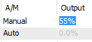
 PID Loop Current Output
These two columns show the current value of the PID loop output, it is the response of the PID loop to a given deviation from setpoint. When the loop is satisfied the output will be small, tending towards 0% when the input signal is satisfied or over setpoint. When the PID loop is under the setpoint the output will increase and eventually hit 100%, it can get no larger than a 100% response. The behavior of the PID loop, whether it is fast acting or slow acting or positive or reverse acting, is determined by the settings further down in this list.
When in “Auto” the PID loop is running and updating according to the real time readings from the sensors and setpoint settings. The user can set the PID loop to manual mode for commissioning and debugging, in this case the value of the output can be edited from the keyboard, overriding the true settings from the sensors and setpoints. Care should be taken to return the PID loop to auto when done or the loop will not update.
|
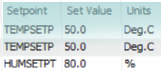
 PID Loop SetpointThis section allows you to configure the setpoint or target for the PID loop, hit enter on the cell in the 'Setpoint' column and type in the variable name or the direct address, VAR1 for example to define where teh PID loop will read its setpoint. Setpoints are normally set up as a variable which is managed with schedules and control basic programs but they can also be simple variables with no logic attached. In this case they are fixed and never change, the user can edit them and manage them from the user graphic screens with the keyboard.
The engineering units for the setpoint and the 'Input' should always be the same, in the example above both are showing as Degrees C. If there is a mismatch the PID loop will still function but it is good practice to have them set up properly. You cannot edit the Units column here however, changing the engineering units is done in the inputs or variables screens.
|
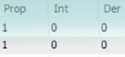
 Proportional, Integral and Derivative TermsThe PID loop gets its name from these three parameters, the Proportional, Integral and Derivative terms showing here. The proportional term can be thought of as the “rigidity” of the PID loop and its response to a deviation from setpoint. A large value will make the valve or damper lazy while a small term will be more hyper active.
The units of the Prop term are in the same units as the feedback sensor, the input range, so if you are in DegC like the example above and have this set to 1, the response of the PID loop will operate from 0 to 100% given a one degree C deviation from setpoint. On the other hand if we have the P term set to 10, that means the temperature will have to deviate by a full 10 degrees C from setpoint to get a 100% response from the PID loop.
The Integral term accumulates error over time and adds it to the PID loop calculation. This can be thought of as a nudge from the PID loop if the temperature is coasting along a small amount above or below setpoint the integral term will accumulate and eventually nudge the damper or valve open a little to achieve setpoint. This size of the I term works the opposite of the P term in that a large value will make the PID more active and a small I term will make the PID loop lazier.
The derivative term allows the PID loop to compensate for a rapidly changing process, if the temperature is quickly approaching setpoint then the D term will increase to slow down the PID response. For common HVAC processes this is not really a concern as the system changes slowly and the D term can generally be left at zero.
Bias is a one time offset added to the PID loop, this is not normally useful and left at zero. It is a feature dating back to the old pneumatic control days to hold a PID loop at a certain value when the setpoint is achieved.
When initially setting up PID loops you will leave the I, D and bias terms at zero because these terms operate behind the scenes and over time there will be windup which can hold the PID at a certain (hard to understand) value for a long while. The room temperature can be right at the setpoint but the valve is staying open at 50% for example, because in fact the valve may need to be open by this amount to maintain the setpoint. Once commissioning is done you can add a small amount of I term. D term is actually left at zero for the most part, as is Bias.
|
 ActionThe PID loop can be either direct acting or reverse acting. When this term is set to positive, the slope of the PID action is positive and a deviation over the setpoint will cause an increase in the PID response. Conversely, a negative acting PID loop will be the opposite, as the feedback sensor shows the process is under the setpoint the PID will increase.
It is convenient to remember that the slope of the cooling PID graph in the previous section slopes up to the right which is a positive slope. The heating PID loop slopes up to the left which is a negative slope. Cool = '+' and Heat = '-'
In the case of air flow control for a VAV damper, the damper should open up when the flow is under setpoint so that would be a negative action.
|
 BiasOut put bias in %. This is the value which the controller will reach at equilibrium if no Integral term is used. If you use the integral term this bias will not be used. This bias feature was useful on the old pneumatic systems where you need a fixed output on the PID loop at setpoint.
|
|