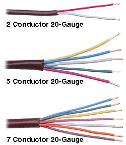
- Allied Cable has some wire specially color coded for thermostat/HVAC use
- It is available in two-conductor up to ten-conductor versions
- Choose 20-ga. for runs up to 250 ft. up to 4A and 18-ga. for runs over 200 ft. up to 8A
This color-coded cable is specifically designed for thermostat/HVAC use, allowing you to easily keep track of what color wire operates what function (i.e. Black=Ground, Red=24VAC, White=Heat, Green=Fan, Yellow=Compressor, and so on).
For heating only systems, 2-conductor cable will often be present, the thermostats in this case can be the mercury switch or other mechanical types which don’t require power. Most systems that provide heating or cooling will have a 4 or 5 conductors cable. Multi-stage systems need cable with upwards of 7 conductors. Use 20-ga. for runs up to 250 ft. up to 4A, 18-ga. for runs over 200 ft. up to 8A.
Notes on grounding: If there is no blue/black wire connected to a COM terminal, the thermostat may be a mechanical or mercury bulb type which do not require power. It may also be a ‘power stealing’ type which doesn’t require the ground or ‘common’ from the transformer since these types scavenge a very small amount of power that returns through the various outputs of the thermostat without actually turning on the equipment. The communicating thermostats from Temco draw more power than can be scavenged so they require a separate COM connection to the transformer. In a new installation, this is not a problem, but in an existing retrofit application you may need to run an extra conductor if there isn’t a spare available in the existing cabling. Sometimes the spare wires will be snipped off up inside the wall so be sure to check the cable all the way up to where the stripping starts for snipped wires. Final note: since you are (probably) running a new communications cable to the Temco communicating thermostat anyway, you will have a GND conductor on the RS485 cable which could be used, in which case you will tie the transformer for the particular HVAC equipment in with the network GND.
Notes on Existing Cabling: In a retrofit situation you will often see the Rc and Rh wires jumpered on an existing installation, in this case a single transformer powers both the heating and cooling equipment which is the most common type. When you see the Rh and Rc as separate conductors which are not jumpered at the thermostat, this means you can (likely) conclude there are two separate transformers, one for the heating equipment and a second for the cooling equipment.
| MARKING | WIRE COLOR (TYP.) | DESCRIPTION |
|---|---|---|
| R | Red | Power, 24 VAC transformer |
| Rc | Red | Power from cooling system, 24 VAC transformer |
| Rh | Red | Power from heat system, 24 VAC transformer |
| C | Black/Blue | Common of 24 VAC transformer |
| W | White | Primary heat call relay |
| E | Brown | Emergency heat relay |
| Y | Yellow | Primary cool call relay |
| Y2 | Yellow | Secondary cool call relay |
| G | Green | Fan relay |
| O | Orange | Change-over relay to cool relay |
| B | Blue | Change-over relay to heat relay |
| A | Heat & Cool active to any relay | |
| L | Emergency heat active lamp | |
| X | System malfunction lamp | |
| P | Defrost control lamp |

