Description
Split Core Current Sensor for Monitoring Single Phase AC Loads
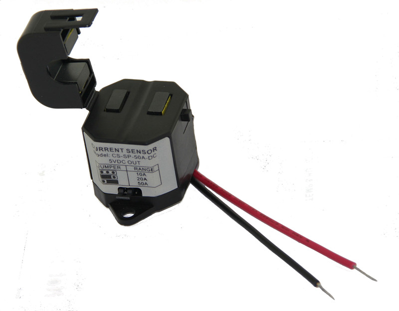
Use this low cost split core current sensor for monitoring single phase AC loads such as fans, pumps, compressors and other mechanical equipment in the building. Typically, mechanical equipment is monitored by wiring to an auxiliary dry contact. This only provides information about the contactor position. By utilizing an analog current sensor you can create smarter alarms such as a slipped fan belt or an impending bearing failure.
The split core current sensor can generate an analog signal directly from the current carrying wire so there is no need for a separate power supply. The split core design is easy to install without interrupting the high voltage wiring, simply open up the sensor core, slip it over the cable and then snap it closed.
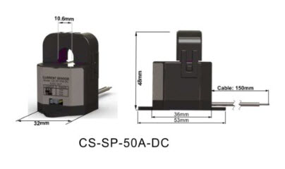
The CT opening is 10mm which is capable of carrying more than 50A. For larger loads and larger cables consider the single phase power meters which are here: Single Phase power meter
Adjustable Current Range and Setup
To set the full scale current range of the sensor, simply adjust the jumper to either the 10A, 20A, or 50A position. For lower current applications you can wrap the current carrying wire through the core more than once. Divide the reading by the number of wraps. So for 2 wraps and the jumper set to the 10A positon the full scale reading is 5A.
It’s important to note that the current sensor shows ‘average current’ while an ammeter reading will show RMS. Even with this disparity the relative current measurements offer valuable data for general monitoring and alarms.
Conclusion: These clamping current sensors measure the AC current of fans, pumps and other HVAC equipment. The 5V analog output signal interfaces easily with PLCs and BMS systems. The analog signal enables rich monitoring and alarming compared to the usual monitoring of dry contacts.
Dimension:
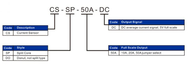
Part Number Scheme:
There are many types of current sensors and they can look deceivingly similar. One CT type outputs 330mV AC at full scale, while another common type for panel meters outputs 5A AC. Both CT types output AC signals that most BMS and PLC systems cannot directly measure or track.
How This Split Core Current Sensor Works
This CT has an onboard rectifier that averages AC signals to produce a DC output proportional to primary current. The circuit derives a small amount of power, just enough to generate the average DC signal, from the secondary coil. This means there is no need for a power supply.
This ‘average’ signal differs slightly from ammeter readings but can be calibrated easily during commissioning. The readings will be more than accurate enough for general monitoring and alarms.
Here are a couple of links to some material which describes the various types in more detail:


