Description
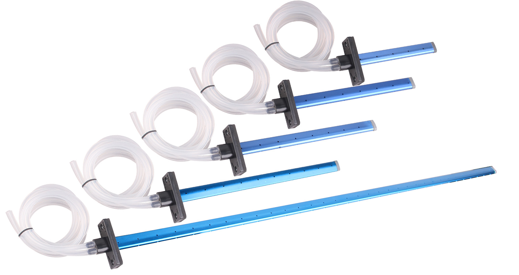
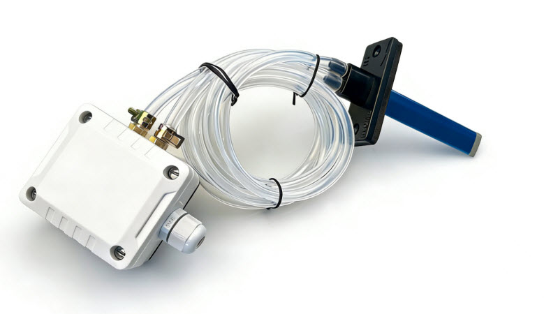
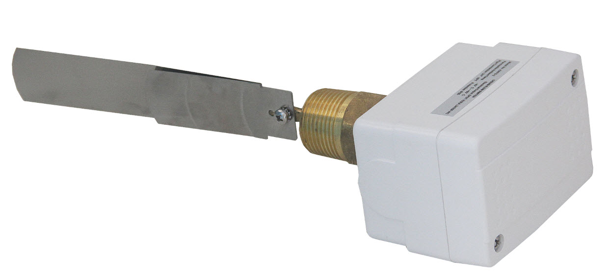
Adjustable Air Flow Paddle Switch
The duct air flow switch provides feedback of air flow in HVAC duct work. It can be directly connected to the control system as a feedback point or interlocked to prevent operation of heating and cooling equipment when there is no air flow. The stainless steel paddle resists corrosion. An adjustable spring tension screw allows setting the air flow trip point from 200 to 1800 FPM (1 to 9.2 m/sec). The paddle can be trimmed down for higher flow applications. The cable enters through the water tight gland, or the gland can be removed and replaced with an EMT or flex connector for wiring with EMT or metal flex.
INSTALLATION
- Use on 8˝ (203 mm) or larger ducts. Trim if needed for smaller ducts.
- Select a suitable location for the switch to be mounted at least 10 duct diameters from fans and 7 diameters from transitions or elbows. Avoid any excess vibration to prevent turbulence while also keeping temperature limits in mind. Horizontal and vertical ducts are both suitable.
- Create a mounting hole and slot the width of the paddle. Also drill four 3/32˝ (2.38 mm) screw holes.
- Insert the air flow switch through the slot and rotate so the arrow is in the direction of air flow. Then use sheet metal screws to attach it to the duct.
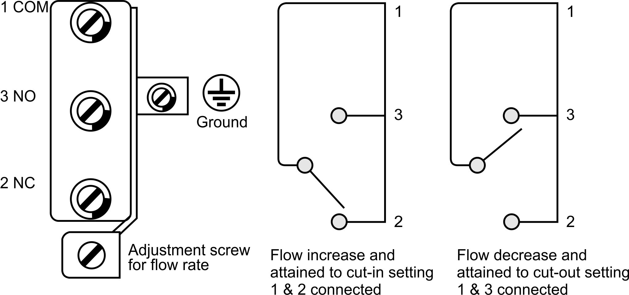
- Loosen the retaining screws and remove the cover to make the electric connections. The SPDT switch has three terminals marked as common, normally open, and normally closed. As air flow passes the trip point, the normally opened contacts will close, and the normally closed contacts will open. A ground screw is provided as well.
- To adjust the trip point, turn the screw located under the enclosure cover. Clockwise rotation increases while anti-clockwise rotation decreases the trip point.
- After all connections and required adjustments are made, replace the cover.
Wiring Connection: